Dunham-Bush explains the importance of acoustics and noise levels when selecting fan coil units

Comfortably Quiet
Fan coil units are a popular choice for engineers when selecting a reliable and efficient source of heating and cooling for a building. They do not require a large central plant to function and with simple proven, controllable technology and installation flexibility, they meet the demands of most commercial and domestic applications.
One of the key factors influencing the choice of fan coil units for buildings, such as offices or hotel bedrooms, is noise. As the selection of fan coil units is governed not only by thermal or air volume fl ow rate requirements, but also by any constraints on the level of noise permitted in the room, the manufacturer is frequently required to select fan coil units based on the predicted noise levels in the room because of the fan coil unit application, however these are influenced not only by the fan coil unit but also by the room itself. During the preliminary design stages, not all the room conditions may be known, but certain assumptions allow the room noise levels to be approximated.
Sound Pressure Level
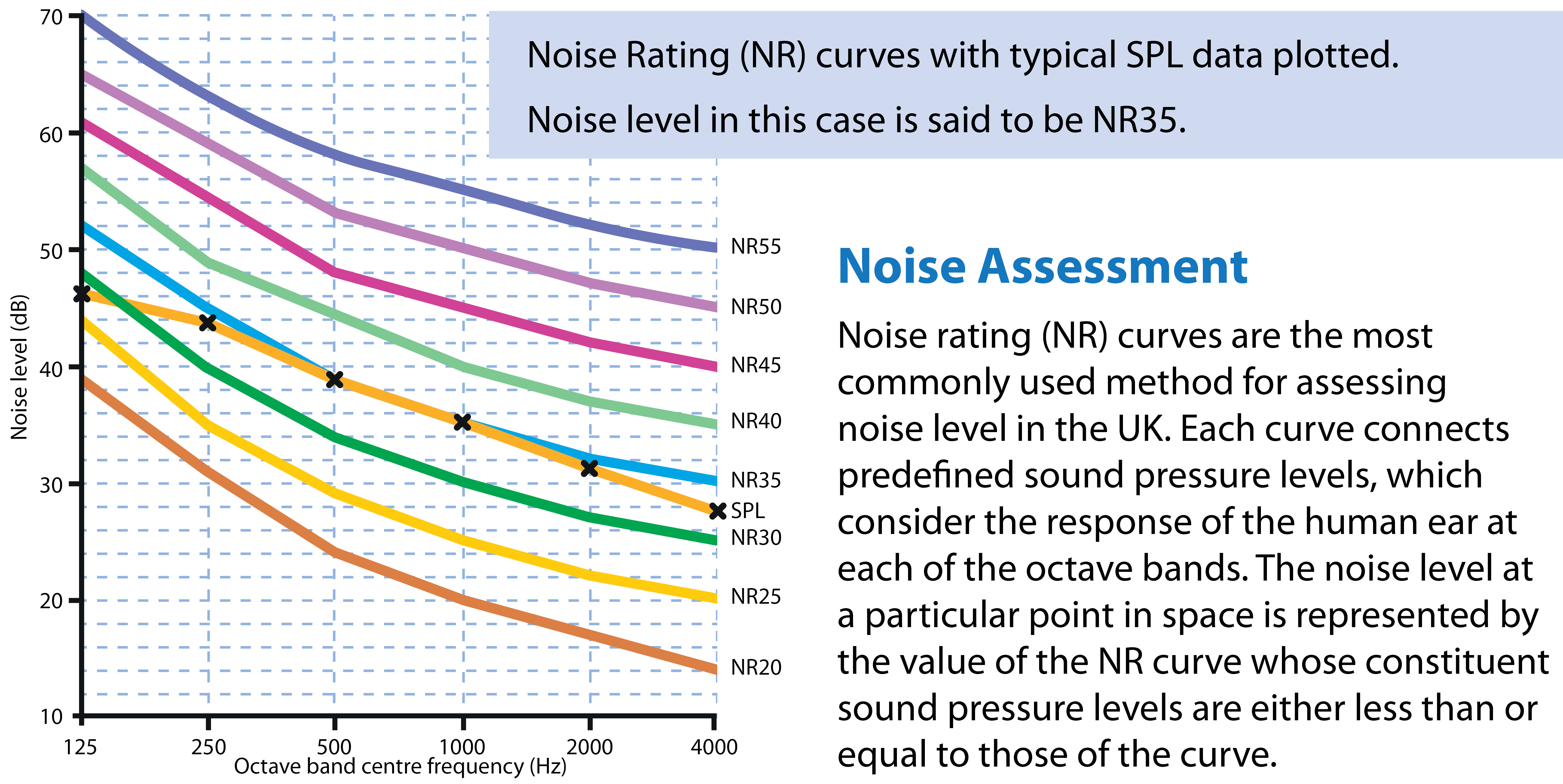
The human ear reacts to fluctuations in air pressure, which we hear as sound. The level of sound heard by the human ear (and measured by an acoustic meter) is known as the sound pressure level (SPL). The ear reacts logarithmically over a very broad range of sound levels and therefore sound pressure levels are quantified on a logarithmic scale relative to a reference sound pressure. They are expressed in decibels (dB) referenced to the pressure corresponding to the threshold of hearing for a typical human ear.
Sound pressure level (SPL) is given by: SPL = 20 Log10 P / Pr where:
P = sound pressure being measured (Pa)
Pr = sound pressure reference i.e. limits of hearing (2 x 10⁻⁵ Pa)
Sound Power Level
In generating sound, the source will expend energy. The rate of transfer of acoustic energy from the source to the medium through which the sound is transmitted is known as the sound power level (SWL). In a similar manner to sound pressure levels, sound power levels are expressed on a logarithmic scale, in dB above the power corresponding to the threshold of hearing for a typical human ear.
Sound power level (SWL) is given by: SWL = 10 Log10 W / Wr where:
W = sound power of source (W)
Wr = sound power reference (1 x 10-12 W)
The Relationship between SWL & SPL
In simple terms, the SWL is the rate at which acoustic energy is transferred to a room from a particular source and the SPL is a measure of the resulting sound at a point within the space. A useful analogy is to consider a heater; the output of a heater is measured as power in Watts (W) and the effect of the output of the heater is measured as temperature in degrees Celsius (°C).
Sound Path
It is important to consider that sound can be emitted from different sources to the listener.
1. Typically inlet and case radiated sound is transmitted through the ceiling into the room space.
2. In-duct sound is carried along the duct and through the supply air diff users and radiates in the room space.
It is also important to consider that sound is transmitted via more than one route when in the room space.
1. The direct sound path is a straight path between source and listener.
2. Reverberant sound paths are any path, beginning at the source, along which sound is reflected off one or more surfaces prior to reaching the listener.
Factors affecting Room Sound Pressure Levels
Certain criteria must be known to determine room sound pressure levels.
1. Sound power levels of the fan coil unit – Sound power levels are typically specified as two separate sets of acoustic data, namely discharge in-duct sound power levels and inlet and case radiated sound power levels.
2. Outlet ductwork – Size, length and type of ductwork together with the quantity of bends incorporated into it affect the level of discharge in-duct sound reaching the supply air plenum.
3. Supply air plenum – Acoustic characteristics of supply air plenum is affected by its size, number of duct connections and whether or not it is acoustically lined.
4. Supply air grille – Type and size of the supply air grille aff cts the level of the radiated discharge sound radiated into the room. High air velocities through the grille or duct may result in noise regeneration at an observed point.
5. Position of the FCU and supply air grille – To prevent the cumulative eff ect of all of the radiating sources of noise, the sources should be separated to distribute the noise evenly.
6. Ceiling construction – Level of inlet and case radiated sound transmitted into the room space is dependent upon the insertion loss of the ceiling.
7. Position of return path – This affects the inlet and case radiated sound passing into the room. The return path should be installed as far as possible from the inlet to the fan coil unit.
8. Room conditions and position of the listener – Sound pressure levels resulting from the direct and indirect component of sound transmitted from the ceiling and the grilles. The indirect or reverberant sound path is affected by both the surface area of the room space and the sound absorption quality of the room surfaces. In addition, the direct path is affected by the distance between the observer and the source.
Big cats perfect for tranquil space at New Louvre, Abu Dhabi

Dunham-Bush has supplied United Arab Emirates based Intercool Central Air Conditioning Ltd with 247 of its Panther and 207 Puma fan coil units to provide heating and cooling at the magnificent new Abu Dhabi Louvre Museum.
Designed by the Paris based architect Jean Nouvel, the museum is organised like a traditional Arab city with separate galleries connected by walkways. A large 590ft radius dome shades the main structure underneath, while allowing shafts of light to rain down through the unusual woven roof. Water surrounds the museum and flows inside, allowing visitors to walk or sit near the interior pools between visits to the museum’s galleries.
The selection of fan coil units was governed not only by thermal or air volume fl ow rate requirements, but also by constraints on the level of noise permitted in the room space. The powerful yet quiet Panther and Puma fan coil units fully satisfied the design brief to create the tranquil environment required in this prestigious building.
The climatic conditions experienced in the UAE demand that only the highest quality materials be used in the museum’s construction and the comfort levels of their visitors were a major consideration for the designers. Dunham-Bush fan coil units combine the very latest design and manufacturing technology to provide the ideal solution to meet precise thermal and noise criteria.
For further information contact Dunham-Bush Ltd
Tel: 023 9247 7700
Email: info@dunham-bush.co.uk